Routing
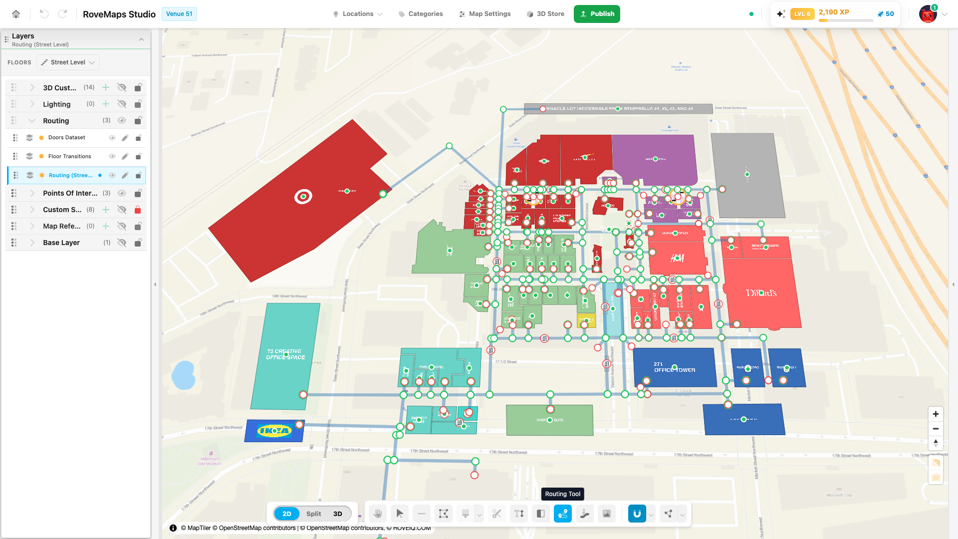
The routing layer is the navigable network that powers wayfinding inside a venue. It’s what drives turn-by-turn navigation (blue-dot positioning), route planning, and the mobile and kiosk experiences that guide visitors from where they are to where they want to go.
You draw and edit this network using the Routing Tool.
How the routing layer works
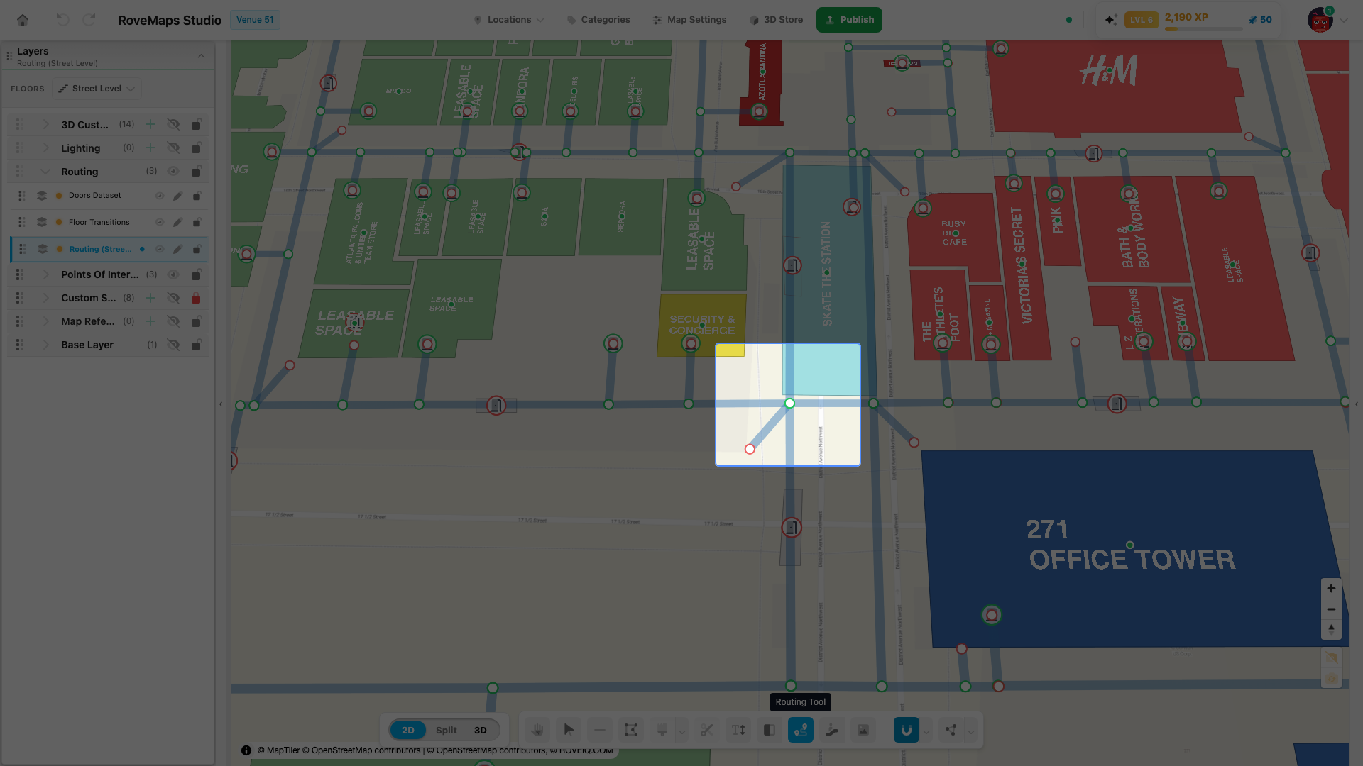
The network is a graph of short, straight segments joined at shared points:
- Segments — each routing line is stored as two-point pieces. A longer corridor is a chain of these short segments, not one long line.
- Nodes (vertices) — the endpoints of each segment. Where segments meet at the exact same point, that point is one shared node, and the route can pass through it.
Each floor has its own routing layer, and the nodes are drawn as editable points while the Routing Tool is open. Outside the tool, only the lines are shown.
Drawing a routing line
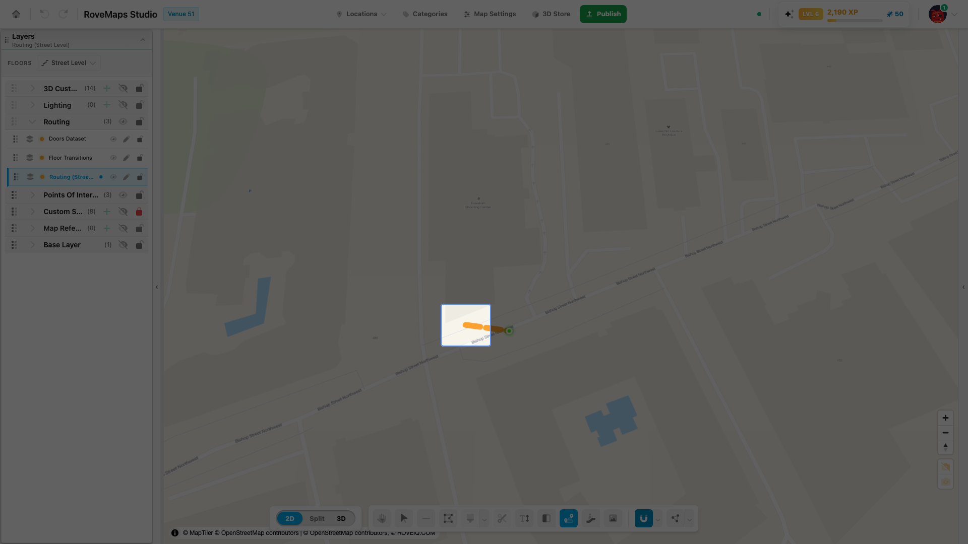
To start drawing a routing line, right-click on the map. From there:
- Left-click places a new node along your path.
- Right-click again submits the line when you’re finished.
- Press Escape to cancel a line before submitting.
While the Routing Tool is active, you’ll notice the camera control for tilt/rotate (bottom-right) is locked. This is intentional — locking the camera lets right-click do double duty, starting a new line and submitting a completed one, without the camera getting in the way.
Reading routing nodes: red vs. green
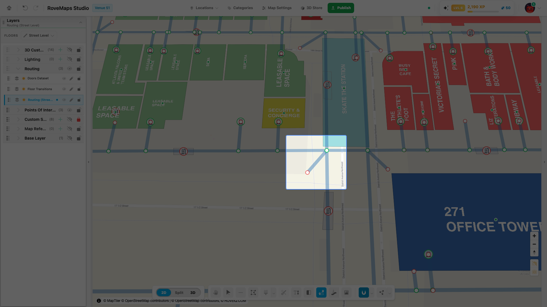
The color of a routing node tells you how it’s connected:
- Red circle — the node connects to only one line. This marks a dead end.
- Green halo — the node is a through-point (the route can continue) or an intersection (the route can head in multiple directions).
Connecting and disconnecting lines
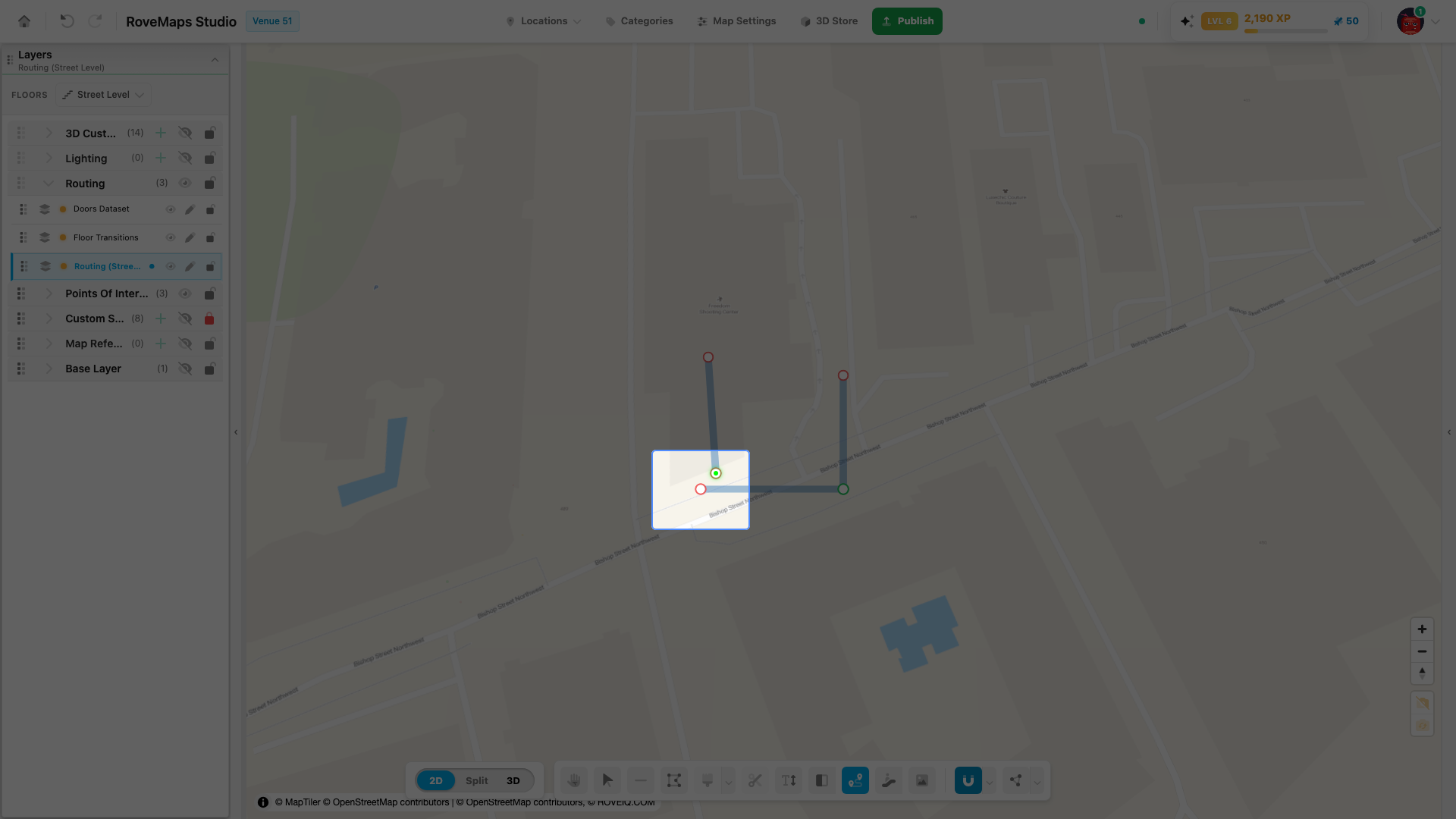
Connecting and welding are controlled by the snapping magnet in the toolbar:
- To connect lines (weld nodes together): turn snapping on, then move routing line ends together. They snap and weld into a single connected node — and while snapping stays on, dragging that node moves every joined endpoint together, so the connection holds.
- To disconnect lines: turn snapping off, then move the lines apart. Only the endpoint you grab moves, so the shared node splits.
Editing your work
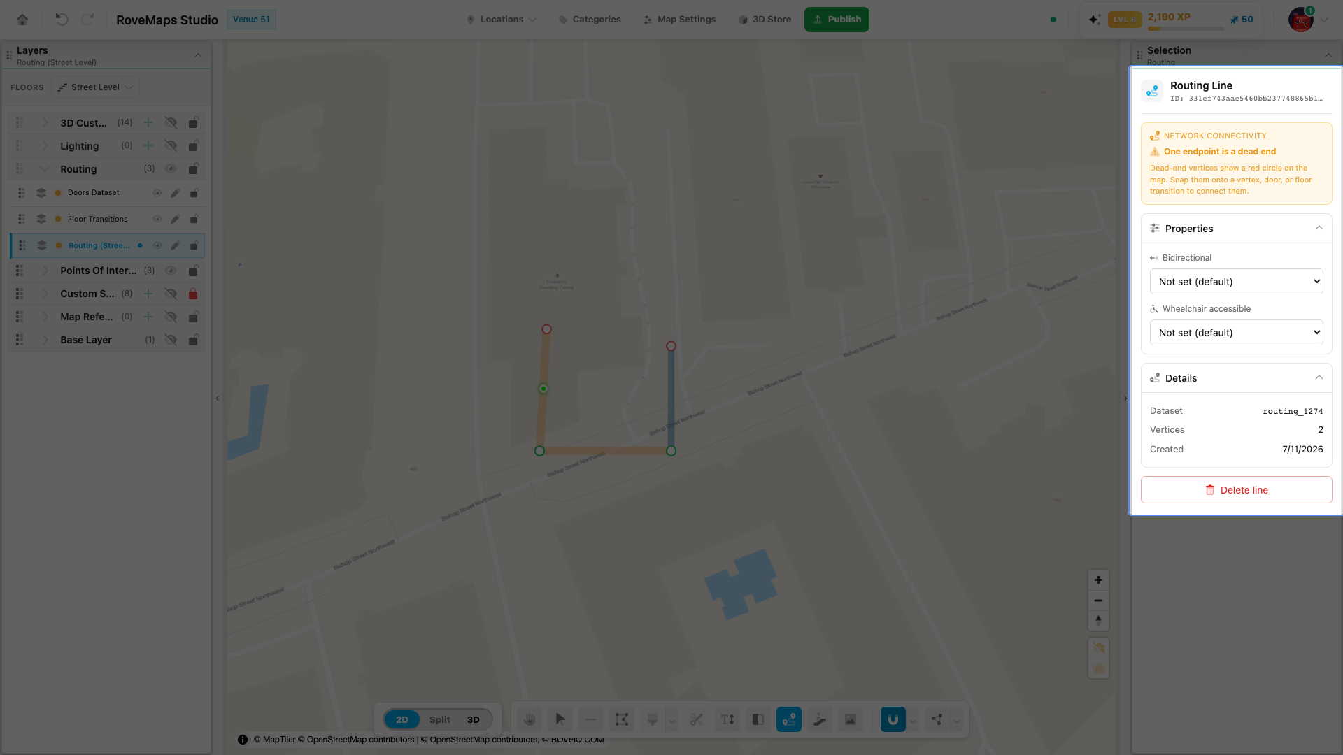
- Select a line — left-click it. The Selection panel shows the line’s network connectivity (including dead-end warnings), lets you set Bidirectional and Wheelchair accessible, and lists its details.
- Delete a line — left-click to select it, then press Backspace or Delete.
- Undo / Redo — use the undo and redo buttons in the top-left. Each editor undoes their own changes.
The shortest path
On mobile, web, and kiosk applications, the user is automatically routed along the shortest path through the network you’ve drawn. You don’t pick routes by hand — you build the network, and the apps compute the best way through it.
Connecting doors to structures
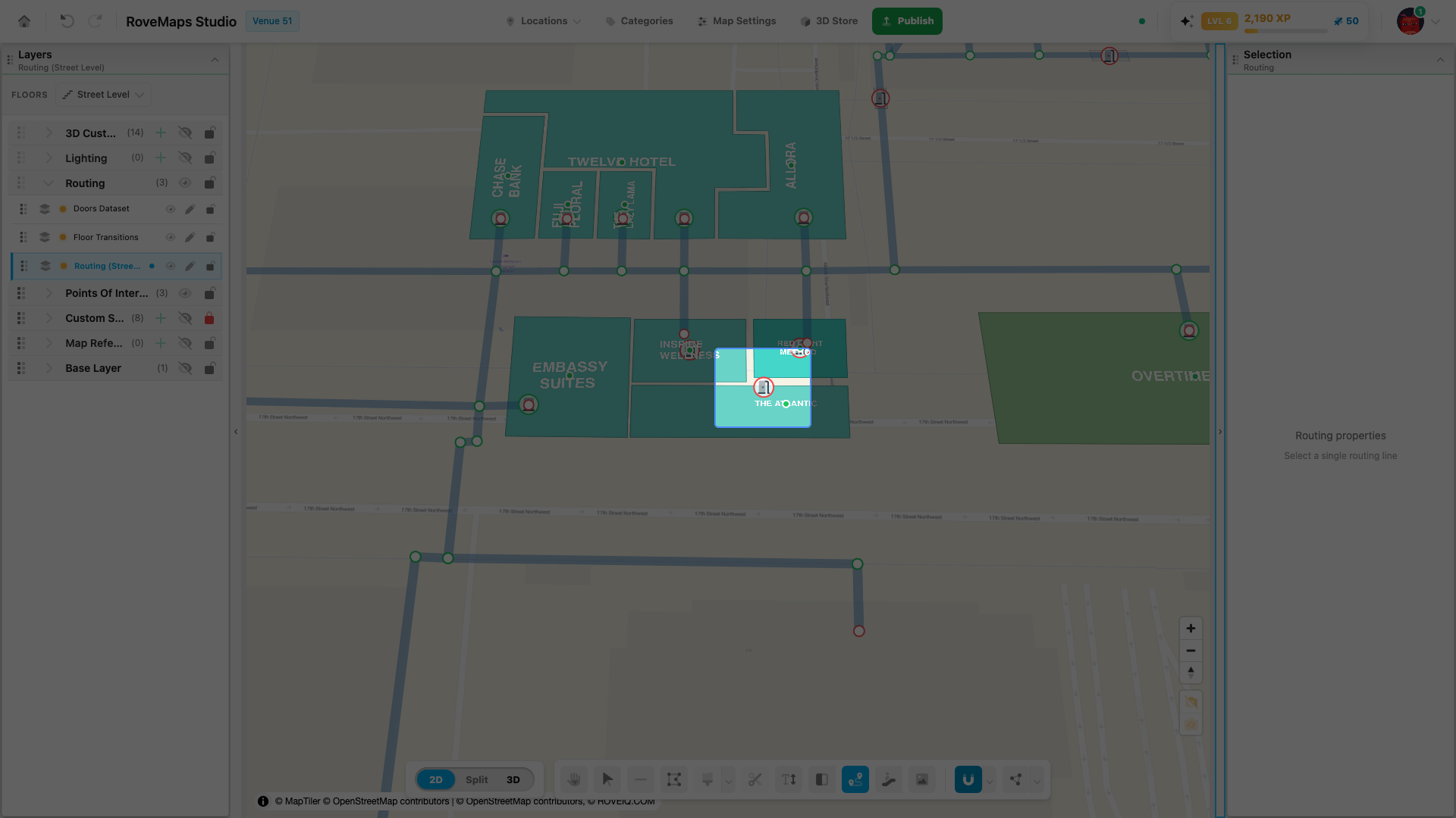
Doors are part of every location — they’re the entrance points into a structure on the map. Every structure you want visitors to route to needs its door connected to a routing line.
To connect a structure:
- Grab an existing routing vertex and drag it over the top of the structure.
- The structure highlights as you hover over it.
- Drop the routing line inside the structure. The structure’s door welds to that position, completing the door entrance — its outline turns green.
The door’s outline color is its status at a glance: green means routing reaches the door; red means it’s not connected yet.
Reminder: a structure with no door connected to a routing line can’t be routed to. If a destination isn’t showing up in navigation, check its door connection first.
Connecting routing to floor transitions
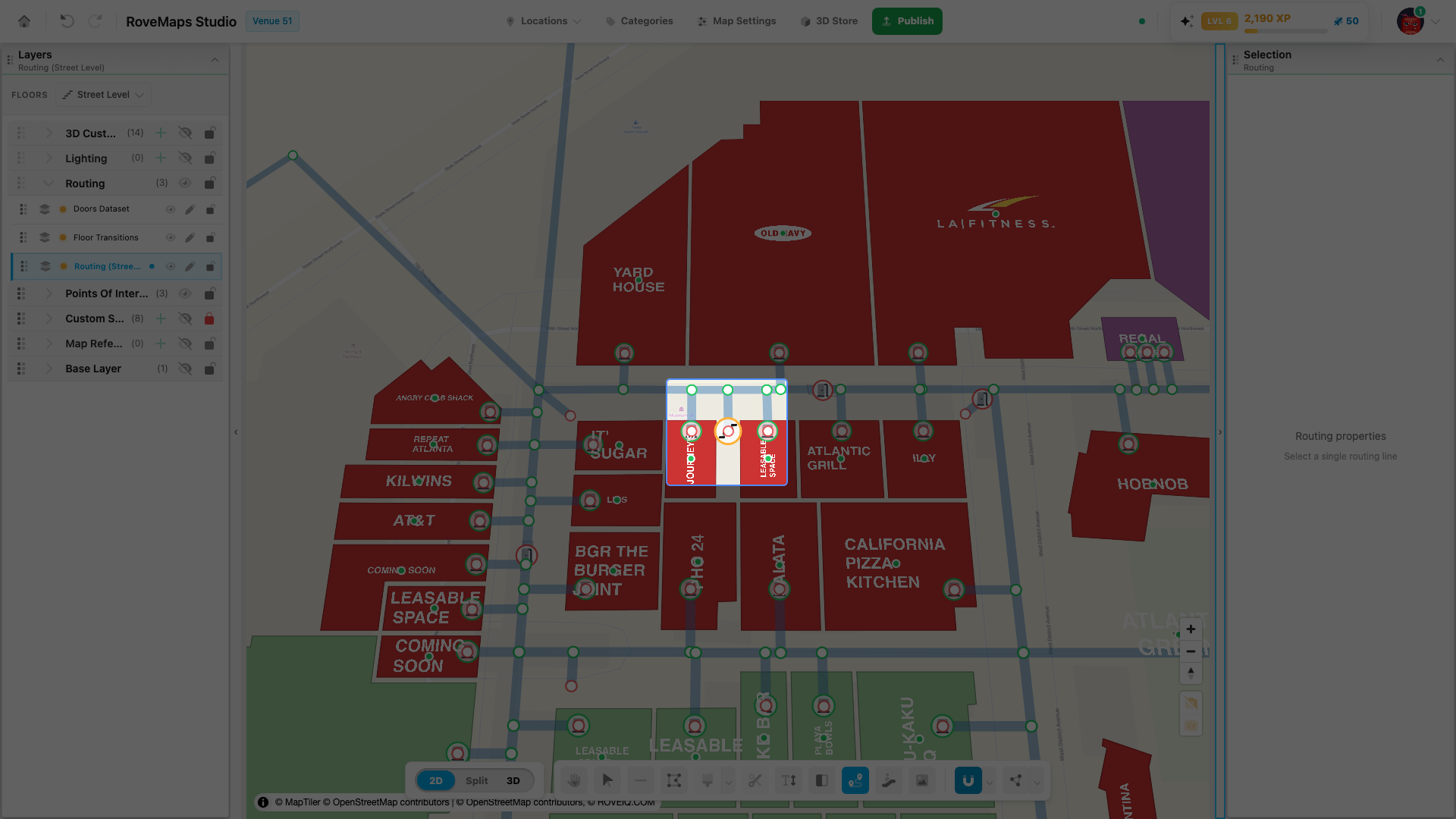
Floor transitions — stairs, escalators, and elevators — let routes move between floors. Connecting them takes one setup step first:
- Make sure you’ve placed a floor transition marker on the map and assigned the floors it serves — see Place a floor transition.
- Grab one end of any routing vertex, or draw a new line.
- With snapping activated, drag or draw it onto the center of the floor transition marker.
The transition’s halo shows how completely it’s routed across its floors:
- 🔴 Red — no routing line is connected on any floor yet.
- 🟡 Yellow — routing is connected on some floors, but not all of them.
- 🟢 Green — routing is connected on every floor. The transition is fully navigable.
Here is the same transition moving through all three states as routing reaches more of its floors:
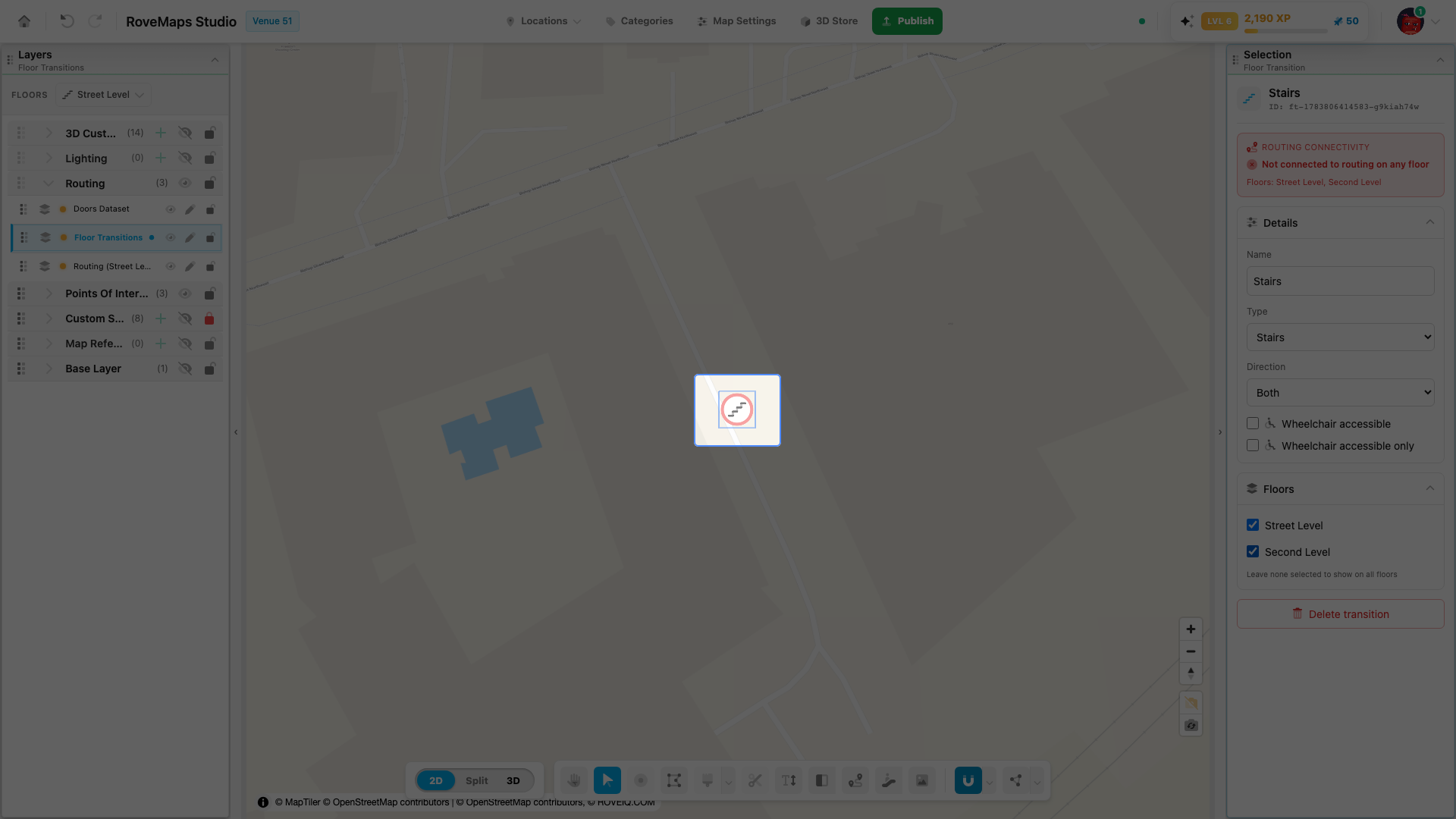
Repeat the connection on each floor the transition serves — switch floors, then snap that floor’s routing onto the same marker. See How floor transitions work for the transition types and properties.
Straightening paths
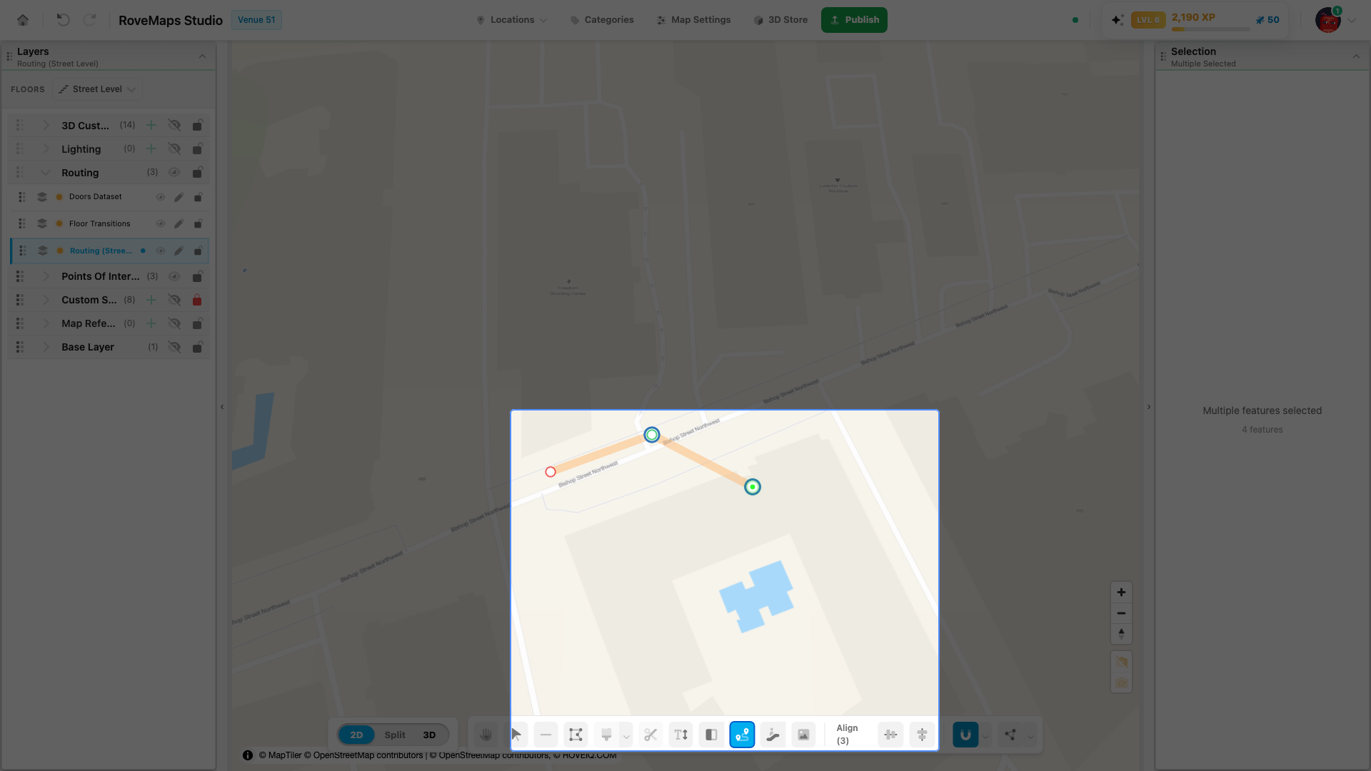
To clean up and align your routing lines:
- Hold Shift and click the nodes you want to align — the selection count appears in the toolbar.
- A horizontal and a vertical align tool appear next to it.
- Use these to straighten lines relative to your current camera angle — so set the camera to the angle you want to align against before straightening.
Navigation settings: color, height, and mobile GPS
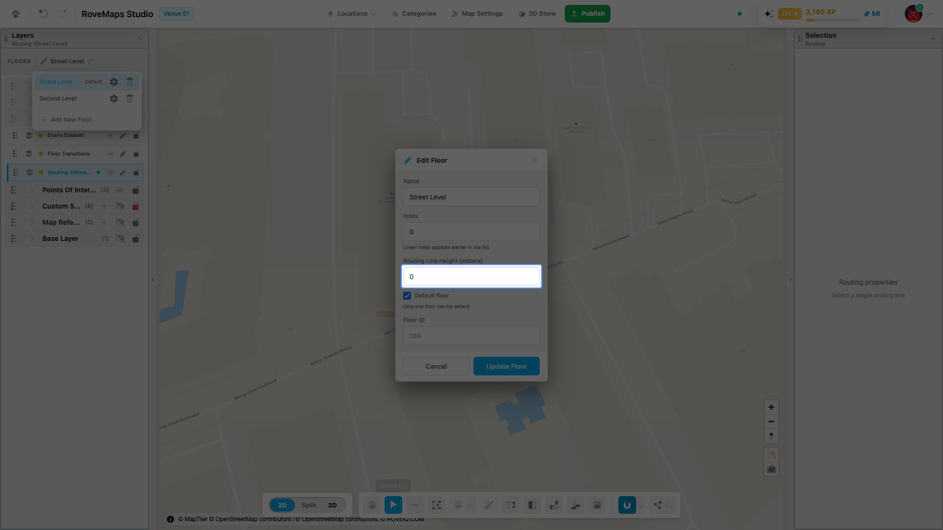
Three settings shape how navigation looks and behaves for end users:
- Routing line color — the navigation line’s color, stroke, 3D sphere color, and line size live on the Routing tab of Map Settings. These are venue-wide.
- Routing line height — how high the navigation line renders above each floor. This is a per-floor setting (Routing Line Height on the Edit Floor drawer) — it lives with the floor, not the routing layer. See Update floor information.
- Mobile GPS (geofence) — the Bounds tab of Map Settings holds the geofence corners: the area where mobile GPS positioning activates for this venue.
Glossary
- Segment — a straight, two-point routing line; the unit the network is built from.
- Node (vertex) — a segment endpoint. Green halo = through-point or intersection; red circle = dead end.
- Snapping magnet — the toolbar toggle that welds endpoints together and keeps welded nodes moving as one. Off = endpoints move independently.
- Door — a structure’s entrance point, where routing connects. Green outline = connected, red = not connected.
- Floor transition — a stairs/elevator/escalator marker that joins the routing networks of the floors it serves. Red/yellow/green halo = none/some/all floors connected.
- Shortest path — the route end-user apps compute automatically through your network.
- Routing Line Height — the per-floor height, in meters, of the navigation animation.